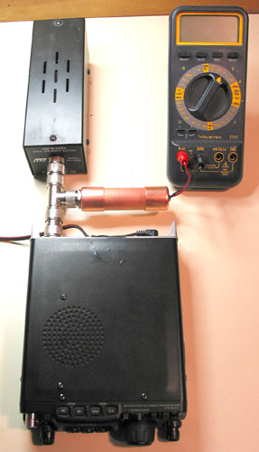
| Here is a photo of the entire setup. The 817 is coupled to a dummy load through a "tee" which also joins the probe |
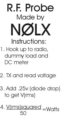
| This is a set of instructions I taped to the side of the tube to remind me how to convert rms voltage into power. I have to include the (rms) voltage drop (.35 x .7071=.25v) across the diode to reflect the true total voltage. |
July 11, 2003
This project came about with the need
to accurately measure the output of my FT-817 at the 500 milliwatt setting. I had
made a contact from Colorado to California with 1/2 Watt on 2-meter
sideband and was eligible for a couple of awards, but I needed to
confirm the actual power. (By the way, it turned out to be 590 mW actual
power for 1,434 miles-per-Watt.)
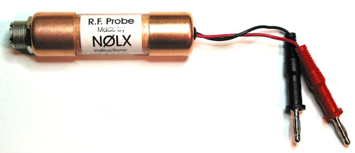
I took the basic schematic from the ARRL
Handbook (2002) and the use of copper tubing from N5ESE's great web
pages. It uses two capacitors, a resistor and a VHF/UHF Schottky diode.
RF is converted to a DC voltage (RMS voltage due to the ratio of the
divider resistor to the meter's impedance) that is read on a digital
voltmeter. A few taps on the keypad of a calculator and I have Peak
Envelope Power.